今まで作ったパーツを元にルーレットを組み立てていきます。
まず、いままでのパーツの復習は以下のとおりです。
divider.vhd
oneshot.vhd
slot.vhd
roullet.vhd
reach.vhd
reach_ctl.vhd
bingo_ctl.vhd
ring.vhd
bingo_ast.vhd
dec_7segled.vhd
何やらいっぱいある感じですが、機能に分割しているからです。
で、トップエンティティは次になります。
slot_game.vhd
-- SLOT TOP Entity
library IEEE;
use IEEE.STD_LOGIC_1164.ALL;

entity SLOT_GAME is
    port(
        CLK         : in  std_logic;
        RESET       : in  std_logic;
        SW          : in  std_logic_vector(2 downto 0);
        LED1        : out std_logic_vector(7 downto 1);
        LED2        : out std_logic_vector(7 downto 1);
        LED3        : out std_logic_vector(7 downto 1);
        DOUT        : out std_logic_vector(3 downto 0);
        ASSIST_LED  : out std_logic
    );
end SLOT_GAME;

architecture RTL of SLOT_GAME is

component DIVIDER
    port(
        CLK         : in  std_logic;
        DIV_CLK_2HZ : out std_logic;
        DIV_CLK_8HZ : out std_logic;
        DIV_CLK_16HZ: out std_logic
    );
end component;

component SLOT
    port(
        DIV_CLK     : in  std_logic;
        RESET       : in  std_logic;
        SW          : in  std_logic;
        STOP_OUT    : out std_logic;
        HIT         : out std_logic_vector(3 downto 0)
    );
end component;

component REACH_CTL
    port(
        REACH_CLK: in  std_logic;    -- リーチ状態の点滅用クロック
        STOP1       : in  std_logic;    -- ルーレットが 0:動 1:止
        STOP2       : in  std_logic;    -- ルーレットが 0:動 1:止
        STOP3       : in  std_logic;    -- ルーレットが 0:動 1:止
        HIT1        : in  std_logic_vector(3 downto 0);
        HIT2        : in  std_logic_vector(3 downto 0);
        HIT3        : in  std_logic_vector(3 downto 0);
        LED_CLK1    : out std_logic;    -- 7SegLEDの点滅クロック
        LED_CLK2    : out std_logic;    -- 7SegLEDの点滅クロック
        LED_CLK3    : out std_logic    -- 7SegLEDの点滅クロック
    );
end component;

component BINGO_CTL
    port(
        RESET       : in  std_logic;
        STOP1       : in  std_logic;    -- ルーレットが 0:動 1:止
        STOP2       : in  std_logic;    -- ルーレットが 0:動 1:止
        STOP3       : in  std_logic;    -- ルーレットが 0:動 1:止
        HIT1        : in  std_logic_vector(3 downto 0);
        HIT2        : in  std_logic_vector(3 downto 0);
        HIT3        : in  std_logic_vector(3 downto 0);
        BINGO_STATUS: out std_logic    -- BINGO 0:× 1:○
    );
end component;

component BINGO_AST
    port(
        STOP1       : in  std_logic;    -- ルーレットが 0:動 1:止
        STOP2       : in  std_logic;    -- ルーレットが 0:動 1:止
        STOP3       : in  std_logic;    -- ルーレットが 0:動 1:止
        HIT1        : in  std_logic_vector(3 downto 0);
        HIT2        : in  std_logic_vector(3 downto 0);
        HIT3        : in  std_logic_vector(3 downto 0);
        BINGO_ASSIST: out std_logic    -- BINGO_ASSIST の点滅
    );
end component;

component RING
    port(
        DIV_CLK     : in  std_logic;
        ENABLE      : in  std_logic;
        DOUT        : out std_logic_vector(3 downto 0)
    );
end component;

component DEC_7SegLED
    port(
        ENABLE      : in  std_logic;
        RESET       : in  std_logic;
        COUNTER     : in  std_logic_vector(3 downto 0);
        LED_7SEG    : out std_logic_vector(7 downto 1)
    );
end component;


signal CLK_2HZ      : std_logic;
signal CLK_8HZ      : std_logic;
signal CLK_16HZ     : std_logic;
signal STOP         : std_logic_vector(2 downto 0);
signal HIT1_TMP     : std_logic_vector(3 downto 0);
signal HIT2_TMP     : std_logic_vector(3 downto 0);
signal HIT3_TMP     : std_logic_vector(3 downto 0);
signal BINGO_STATUS : std_logic;
signal LED_TMP      : std_logic_vector(2 downto 0);

begin

    U1:DIVIDER      port map (CLK,CLK_2HZ,CLK_8HZ,CLK_16HZ);
    S1:SLOT         port map (CLK_16HZ,RESET,SW(0),STOP(0),HIT1_TMP);
    S2:SLOT         port map (CLK_16HZ,RESET,SW(1),STOP(1),HIT2_TMP);
    S3:SLOT         port map (CLK_16HZ,RESET,SW(2),STOP(2),HIT3_TMP);
    U2:REACH_CTL    port map (CLK_2HZ,STOP(0), STOP(1), STOP(2), HIT1_TMP,HIT2_TMP, HIT3_TMP,LED_TMP(0), LED_TMP(1), LED_TMP(2));
    U3:BINGO_CTL    port map (RESET,STOP(0), STOP(1), STOP(2), HIT1_TMP,HIT2_TMP, HIT3_TMP,BINGO_STATUS);
    U4:BINGO_AST    port map (STOP(0),STOP(1), STOP(2), HIT1_TMP,HIT2_TMP, HIT3_TMP,ASSIST_LED);
    U5:RING         port map (CLK_16HZ,BINGO_STATUS,DOUT);
    D1:DEC_7SegLED  port map (LED_TMP(0),'1',HIT1_TMP,LED1);
    D2:DEC_7SegLED  port map (LED_TMP(1),'1',HIT2_TMP,LED2);
    D3:DEC_7SegLED  port map (LED_TMP(2),'1',HIT3_TMP,LED3);

end RTL;
ここで、次のように
    D1:DEC_7SegLED  port map (LED_TMP(0),'1',HIT1_TMP,LED1);
    D2:DEC_7SegLED  port map (LED_TMP(1),'1',HIT2_TMP,LED2);
    D3:DEC_7SegLED  port map (LED_TMP(2),'1',HIT3_TMP,LED3);
RESETに'1'をつなげているのは、
リセットを押した時に7セグが消えずに0を表示させるためです。
チャタリングカットを入れていないのは、
スイッチを一度押せばカウンタは止まってしまうので、
チャタリングを考慮する必要がないからです。
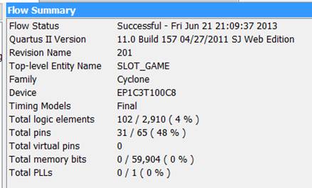
コンパイルした結果が下図です。
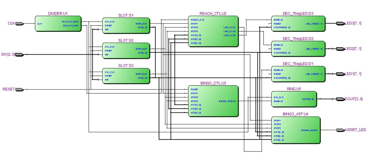
回路図(RTL_VIWER)は下図です。
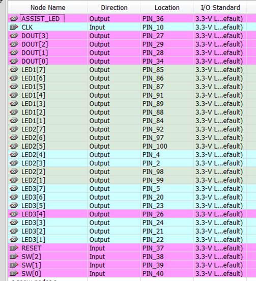
ピン配置は下記です。